
CROSSNIQ
New Feature/Optimization - Dynamic Field Sizing
Hi, all! Welcome to the first serious devlog post for CROSSNIQ! I'll try to post ~weekly as I add in new optimizations, features, or gameplay mechanics, explaining the gist of them without getting too technical/code-oriented.
Today, I'm gonna talk about how I recently improved the playfield generation system to be dynamic, rather than the hard-baked system that I used for the initial prototype.
The playfield for CROSSNIQ (where the tiles are, versus areas of the screen cordoned off for UI) is planned to always be a perfect square, as are the tiles. The higher the difficulty, the larger the playfield's dimension will be (8x8 tiles, 10x10, 15x15, etc.). In the initial prototyping phase, I gauged a good estimate for the optimal physical screen size of the playfield (in cm, not pixels!) by tracing the dimensions of an actual iPad screen onto a piece of paper and taping it to my monitor! While this method was crude, it did create an effective guide as to what an optimal playfield size would be for both mouse and touch controls.
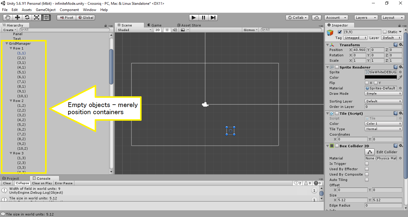
After I blocked out the playfield size, I had to come up with a quick way of actually laying out a grid to test. Unfortunately, I decided to go with hand-positioning and baking 100 tiles (10x10) by hand for the initial prototype. This took an entire night, but creating the codebase architecture necessary to set up a more efficient system before I even had a field to test seemed like a potentially huge waste of time; ultimately, for the reasons of getting up and running quickly, I think laying out the tiles by hand was the right decision. After I finished, the newly-minted GridManager (a manager that keeps track of the worldspace positions of the playfield grid, assigns them to a 2D coordinate system, and provides helper methods for quick conversion of things like directions, coords-to-worldspace, etc.) looked something like this:
Multiple playfield dimensions, increasing with difficulty, were planned from the start of the project. As time went on, it became clear to me that manually placing each one for each size for each potential mode would be a fool's errand. So, I decided to create a system that would populate a given playfield size dynamically with a number of tiles specified as (for now) an Inspector variable.
And then, a week later, the playfield looked a little more like this - simply the core GridManager object and a rect transform!
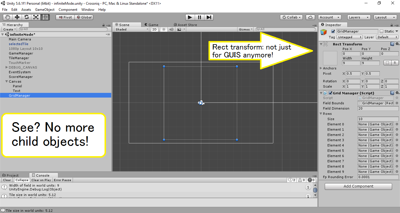
While those Unity devs among you may be familiar with rect transforms within the Canvas UI system, it can also be used as a general-purpose component in world space! Due to its ease of use in the Inspector, it was the perfect fit to define the playfield area.
But what about the actual tile generation?
Well, the pseudocode within the GridManager goes a little like this...
- GIVEN...
- A perfectly square Rect Transform defining our playfield area (no rectangles!)...
- The size of the prefab Tile object's side length in world units (can get from rend.sprite.bounds.x * 2)...
- The dimension of our playfield, e.g. number of tiles in a row or column (int - whole numbers only)
- WE MUST...
- First, measure the width of the rect transform in world units.
- Then, divide that width by the playfield dimension. This is our [proposed tile dimension in world units].
- Then, take ([proposed tile dimension in world units]/[actual tile prefab dimension in world units] to get a scale percentage.
- This percent is the [ACTUAL TILE SCALE]. The tile prefabs will be scaled to this on the x and y (z doesn't really matter) to be properly sized.
- Give that info to the Tile Manager to set tile scale properly on spawn. (as the name implies, it's the manager responsible for spawning/clearing/wrapping tiles, checking for crosses, object pooling, etc.)
- Once that info is established, we must slice up the grid.
- Starting in the LOWER LEFT CORNER (worldpos vector3) of the rect transform, add + [HALF OF SCALED TILE SIDE LENGTH IN WORLDSPACE] to the x and y. This will give us our (0,0) point - we'll want to store it in the proper (0,0) spot in the grid manager's coords-to-worldspace array, as well as store it in a local variable to use below.
- Start a doubly nested for loop (gasp!): i for columns, j for rows. Iterate through while adding [WHOLE OF SCALED TILE SIDE LENGTH IN WORLDSPACE] to the temp vector on both x and y, saving it to the proper (row,column) spot on each iteration. This loop will properly populate the grid positions.
- Done!
With all of that mouthful, we can do things like this!
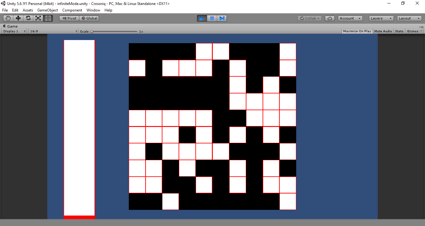
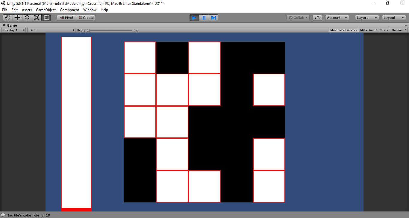
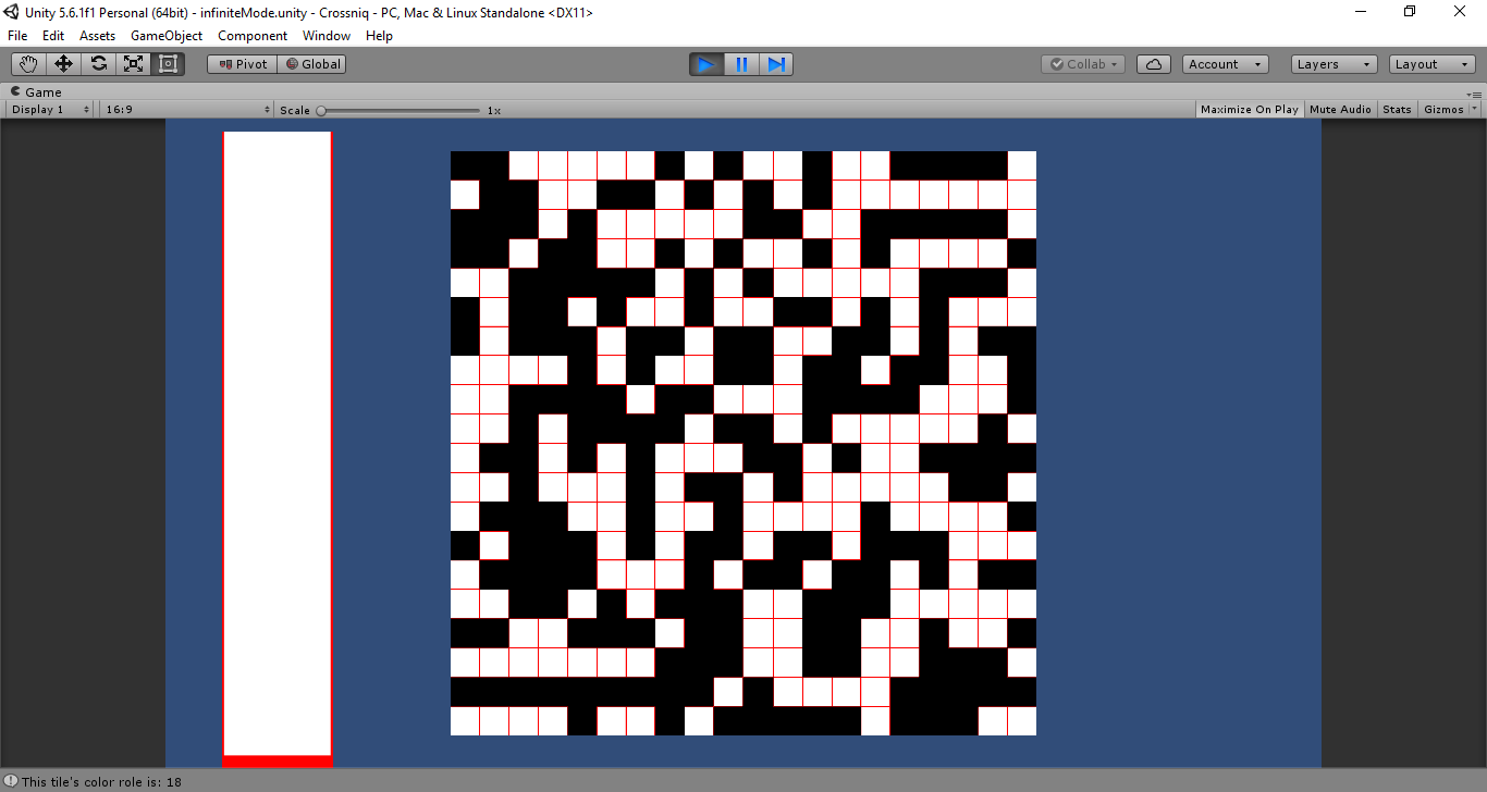
All sized dynamically, either at runtime (through a proposed future "game settings"/"game config" container object, perhaps...) or via the Inspector! The only limits are a). what is practical for the player, and b). the ability to make a cross (by that logic, 3x3 is the minimum possible size, though the minimum recommended one is a bit higher).
See you (hopefully) next week or sooner, everyone! Hope this reminded all of you how a little hard work ultimately creates a lifesaver when you go from manual positioning to a dynamic system.
How did I do?
This was my very first real devlog post, so please give me (constructive) feedback in the comments. Did I go into too much detail? Too little? Wanna see actual code? Please let me know!
Leave a comment
Log in with itch.io to leave a comment.